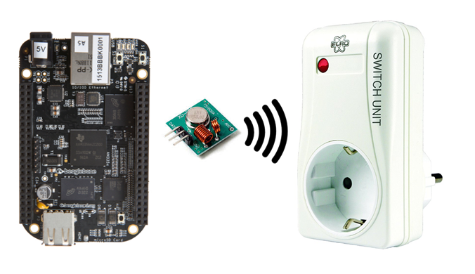
Using the BeagleBone as 433 MHz Transmitter to switch Power Outlets for ‘Home Automation’ needs.
This tutorial explains in detail how to set up the BeagleBone with a low-cost 433 MHz transmitter, and shows where to find and how to setup the necessary software for Debian Linux. The solution works only on a BeagleBone, because the TI AM355x Sitara PRU is part of the solution.

So if the picture above doesn’t tell you anything there is no need for you to read any further.
Introduction
I was searching the web for hints how to control RF power outlets with 433 MHz transceivers with the BeagleBone, but I mostly found a lot of pages explaining how it works with Raspberry or Arduino. I assume that I am not the only one who wants to use the BeagleBone to control power outlets. That’s why I thought it might be a good idea to share my experiences with the community (means you).
Step 1: Hardware
If you found one of the mentioned Raspberry or Adruino tutorials also, you are well aware of the fact that a 433 Mhz Transmitter is necessary for the “physical layer” of our project. I got my one from Amazon (Germany) here. I ordered a set of three pairs plus a bag of 10 antennas because the whole set cost almost nothing.
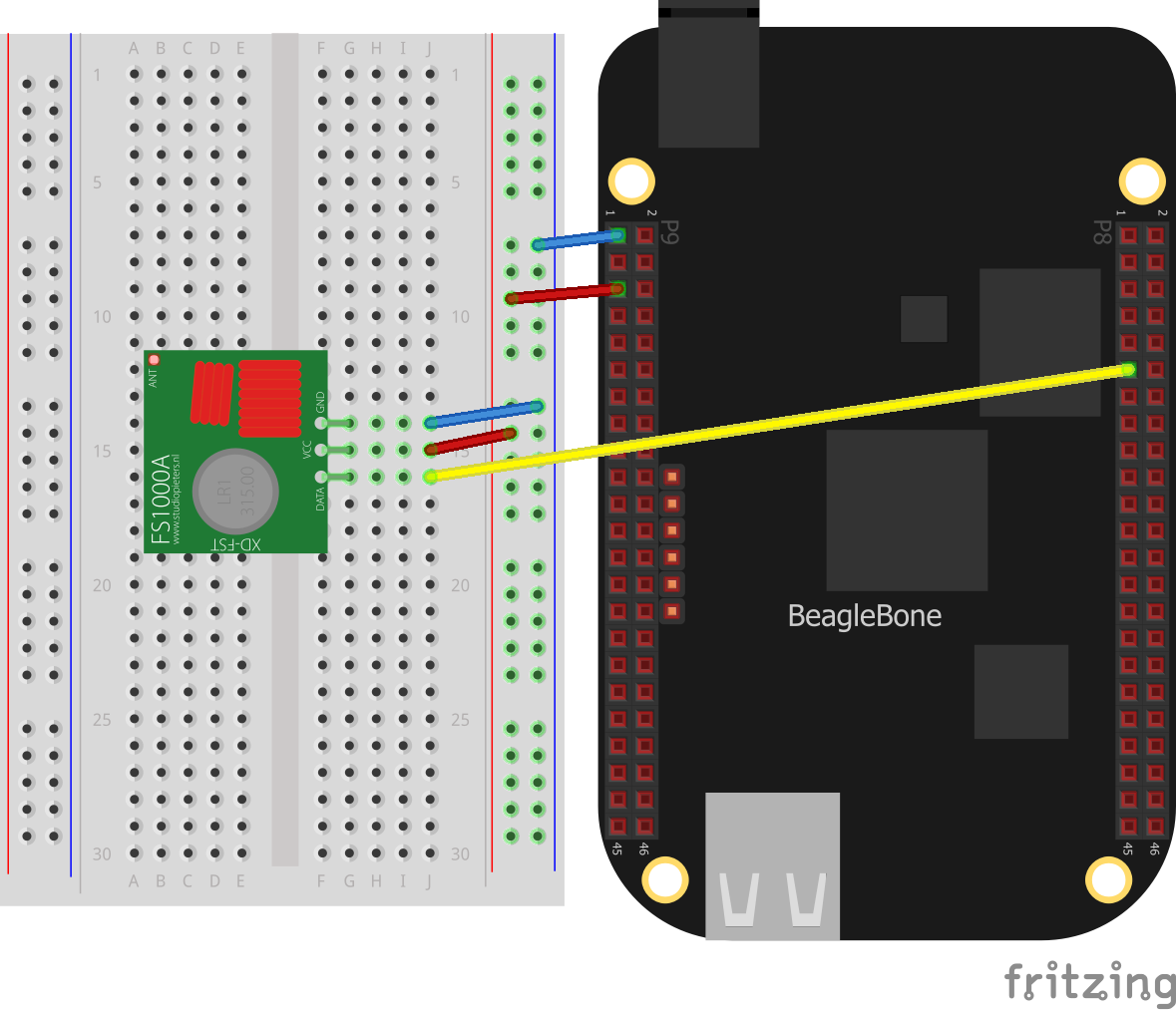
The picture below shows how the RF Transmitter must be connected to the BeagleBone.

By the way: When I was searching for a tool to create a simple schematic like the one above, I ran into the fritzing software. Really cool stuff! Have a look!
Here is the corresponding signal table to show the connection beween our BeagleBone and the transmitter circuit.
| Beaglebone | Transmitter | Function |
|---|---|---|
| P9_1 | GND | Ground |
| P9_5 | VCC | + 5V Power |
| P8_11 | DATA | Output Signal BB |
Step 2: Preparation
I don’t think that it makes a big difference which Linux version you use. I have a pretty new Debian on my board. But since we need to clone some packets with git, you want to make sure that git is installed on your machine:
root@blackbone:~# apt-get update
root@blackbone:~# apt-get install git-core
As you might have noticed I work with the ‘root’ user on my BeagleBone. Some may say:
Warning! Working with ‘root’ is a serious security breach! Never do this! Never ever!!!
But I think “security breach? On my development board? What the heck…”. I’m just too lazy to type sudo over and over again. Besides that, the ‘rfsend’ program described down below needs root rights anyway.
Step 3: PRU Tools and Librarys
The next thing we need is a toolchain for the BeagleBone Controller PRU. I am honestly not aware what comes preinstalled with the actual Debian because I didn’check. Feel free to check yourself. I used a git project which cou can find here.
Download and compile the project with the following commands:
cd ~
git clone git://github.com/beagleboard/am335x_pru_package
cd ~/am335x_pru_package

make all
make install
Note: You’ve noticed that I’m still working as ‘root’ in the /root home directory, right?
After a successful build, the PRU Assembler (needed for the next step) is present and some librarys were created. The librarys end up in the directory /usr/local/lib/ but should be in /usr/lib/ instead to make the next step possible. I simply copied them over.
cp /usr/local/lib/libprussdrv.a /usr/lib/libprussdrv.a
cp /usr/local/lib/libprussdrvd.a /usr/lib/libprussdrvd.a
cp /usr/local/lib/libprussdrvd.so /usr/lib/libprussdrvd.so
cp /usr/local/lib/libprussdrv.so /usr/lib/libprussdrv.so
Step 4: ‘rfsend’ Software
Now we need to clone and build the rfsend software. You will find it here. Download and build it with the following commands:
cd ~
git clone git://github.com/jonlidgard/rfsend
cd ~/rfsend

make
At this point allow me to thank Jon Lidgard for his work! I believe I found his project only one day after he published it. So it seems to be a pertty fresh contribution. I was almost ready to give up when I was looking for a BeagleBone solution because I could’t find one. But then I discovered Jon’s solution which saved my life so to say. Thanks for that!
In case the installation of the PRU tools and librarys in Step 3 were successful, it should also be possible to build Jon’s code right away.
Step 5: Enable PRU Output
When my interpretation of the ‘./rfsend –help’ output is correct we need to do two more things:
- Enable a ‘Universal IO Cape’ in the BeagleBone config and
- Enable our output pin P8_11 for PRU usage.
The first thing is to open the file /boot/uEnv.txt with your favourite editor and to find and uncomment the following line to use our ‘cape’:
###pru_uio (4.4.x-ti & mainline/bone kernel)
uboot_overlay_pru=/lib/firmware/AM335X-PRU-UIO-00A0.dtbo
After that and before we continue with the next step it’s necessaty to
reboot
the system.
The second thing (and this took me a while since I’m not that familiar with the BeagleBone GPIO usage) is to execute a command which enables the output:
config-pin p8.11 pruout
To check if the pin is in the desired mode you can use:
cat /sys/devices/platform/ocp/ocp:P8_11_pinmux/state
Step 6: Test Execution
Now the miracle happens. It’s time to seperate the boys from the men. With
./rfsend 1119313
the lamp of our (my) test installation is switched on, and with
./rfsend 1119316
it is possible to switch it off!
Isn’t that something? Just a few days of research and one is able to switch the light on and off? Wow! I love technology! Great to be a nerd! Time for a beer…
Now you might ask where I got the code 1119313 which accidently fits to my test installation? To be honest: I also own a Raspberry PI and there are projects out there (for example this one) which come with a tool named RFSniffer. That helped a lo lot to find the correct code.
In my case the test installation is a ELRO power outlet. The system code is ‘10101’ and the unit I used is addressed with ‘C’.
So if you don’t have a Raspberry PI with RFSniffer, just use the same setup (‘10101’ as system code and ‘C’ as unit code) and you should be fine. If you are interested in calculating a code you need to read the next step.
Step 7: Decimal Code Calculation
The telegram which goes out on the wire looks like this:

The image above I borrowed here. I herby ask for forgiveness.
- The complete frame is 32 bits long.
- 8 bits are sync and 24 bits are net data.
- The pulse length is defined to be between 300 and 500 microseconds
- The sync is 1 pulse high and 31 pulses low
- The ‘0’ is 1 pulse high and 3 pulses low
- The ‘1’ is 3 pulses high and 1 pulse low
Now taking my two codes for ON and OFF and showing them in hexadecimal notation, we would get:
| CODE | DECIMAL | HEXADECIMAL |
|---|---|---|
| ON | 1119313 | 0x111451 |
| OFF | 1119316 | 0x111454 |
Now with the 3 Byte hexadecimal code 11 14 51 we would get a 24 bit net data frame.
Consider the DIP-switch settings of our hardware beeing encoded with 2 bits per switch position, this woud be in my case ‘ON OFF ON OFF ON’ for the house or system code ‘10101’ and ‘OFF OFF ON OFF OFF’ for power outlet ‘C’. On top we have one position (2 bits) for the ‘switch off’ command and another position (2 bits) for ‘switch on’ command.
A switch position ON is (presumably because of pull down logic) represented as a two bit value ’00’ whereas a switch position OFF is encoded as ’01’.
Having 5 x 2 bits for the system code and another 5 x 2 bits for the power outlet selection plus 2 bit for the ‘On Command bit’ plus 2 bit for the ‘Off Command bit’ this adds up to a total of 24 bits.
The three parts in switch representation are shown in the table below:
| part | SWITCH | BINARY |
|---|---|---|
| System Code | ON OFF ON OFF ON | 00 01 00 01 00 |
| Power Outlet | OFF OFF ON OFF OFF | 01 01 00 01 01 |
| Off Command | Low | 00 |
| On Command | High | 01 |
If we bring the 24 bits together we get a binary 0001 0001 0001 0100 0101 0001 which is in hex 11 14 51 or 1119313 decimal.
Here is another attempt to explain this, but since my ‘WordPress Twenty Thirteen’ theme is a bit narrow it’s hard to read. Therefore it might be easier to download the image and open it elsewhere.

That’s it folks…
Thanks for your attention. I hope this information is useful for somebody. Feel free to leave a comment down below, but please don’t ask any questions. I won’t have the time to answer them anyway.
Have fun
Joerg